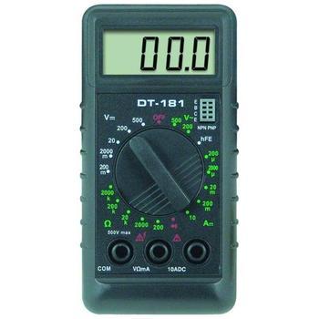
How to use a multimeter
 Grounding resistance tester is a common instrument for measuring grounding resistance. It is also an indispensable tool for acceptance inspection of electrical safety inspection and grounding projects. The new disconnection alarm function, that is, open circuit alarm, can be used to know if the instrument is working in a normal test state. The new disconnection alarm function is an open circuit alarm.
 Under normal circumstances, test the grounding resistance, need to bury the grounding body, lead out the grounding level, in order to reliably ground the instrument and equipment. In order to ensure that the grounding resistance meets the requirements, a dedicated grounding resistance tester, such as the Japan Kyoritsu 4105A grounding resistance tester/Kyoritsu 4102A, is usually required for measurement. Or use a relatively expensive clamp ground resistance tester.
However, in use, a dedicated grounding resistance tester is expensive, and it is inconvenient to purchase it. Can the multimeter be used to measure the grounding resistance? The author used a multimeter to test the grounding resistance in soils of different soil quality, and the data measured by the multimeter and the dedicated grounding. The data measured by the resistance tester are compared and the two are very close. The specific measurement method is as follows:
Find two round bars of 8mm and 1m in length. Use one end of the round bar as the auxiliary test bar and insert them into the ground 5m away from both sides of the grounding body to be measured. The depth should be more than 0.6m, and the three should be kept in a straight line.
Here, A is the grounding body to be measured, B and C are the auxiliary test bars, and then A and B are measured with a multimeter (R*1 block); the resistance values ​​between A and C are denoted as RAB, RAC, and RBC, respectively. The grounding resistance of the grounding body A can be obtained by calculation.
Grounding resistance refers to the contact resistance between the grounding body and the soil. Let A, B, and C be the grounding resistances for RA, RB, and RC, respectively. Set the resistance of the soil between A and B to RX, because the AC and AB distances are equal, and the soil resistance between A and C is also RX; because BC=2AB, the soil resistance between B and C is approximately 2RX, then:
RAB=RA+RB+RX. . . . . .
1RAC=RA+RC+RX. . . . . .
2RBC=RB+RC+2RX. . . . . .
3 Will be 1 +2 - 3: RA = (RAB + RAC - RBC) / 2. . . . . . 4
Type 4 is the calculation formula of grounding resistance.
The actual measurement example: The data of a certain grounding body measured as follows: RAB = 8.4 ∩, RAC = 9.3 ∩, RBC = 10.5 ∩. then:
RA=(8.4+9.3-10.5)/2=3.6(∩)
Therefore, the grounding resistance of the measured grounding body A is 3.6 ∩.
It is worth noting that before measurement, three grounding bodies A, B, and C need to be sanded and polished to minimize the contact resistance between the test leads and the grounding body to reduce errors.
Grounding resistance tester is a common instrument for measuring grounding resistance. It is also an indispensable tool for acceptance inspection of electrical safety inspection and grounding projects. The new disconnection alarm function, that is, open circuit alarm, can be used to know if the instrument is working in a normal test state. The new disconnection alarm function is an open circuit alarm.
Turntable Ring Gear,Slewing Bearing,Gear Ring Bearing,Slew Ring Bearing
Slewing Bearing Co.,Ltd. , http://www.slewingring-bearings.com